
LCD Display
Installing Adafruit SPI LCD library:
sudo pip3 install adafruit-circuitpython-rgb-display
Copy the example from the readme at https://github.com/adafruit/Adafruit_CircuitPython_RGB_Display. It needs some modifications to match our pinout and to drive the backlight and reset pins:
import time
import busio
import digitalio
from board import SCK, MOSI, MISO, D8, D22, D25, D27

from adafruit_rgb_display import color565
import adafruit_rgb_display.ili9341 as ili9341


# Configuration for CS and DC pins:
CS_PIN = D8
DC_PIN = D22

# Backlight is under GPIO control on our board, needs to be driven or we won't see anything
backlight = digitalio.DigitalInOut(D25)
backlight.direction = digitalio.Direction.OUTPUT
backlight.value = True

# The reset pin is under GPIO control and defaults to input pull-down which holds it in reset
reset_pin = digitalio.DigitalInOut(D27)
reset_pin.direction = digitalio.Direction.OUTPUT
reset_pin.value = True

# Setup SPI bus using hardware SPI:
spi = busio.SPI(clock=SCK, MOSI=MOSI, MISO=MISO)

# Create the ILI9341 display:
display = ili9341.ILI9341(spi, cs=digitalio.DigitalInOut(CS_PIN),
                        dc=digitalio.DigitalInOut(DC_PIN))

# Main loop:
while True:
    # Clear the display
    display.fill(0)
    # Draw a red pixel in the center.
    display.pixel(120, 160, color565(255, 0, 0))
    # Pause 2 seconds.
    time.sleep(2)
    # Clear the screen blue.
    display.fill(color565(0, 0, 255))
    # Pause 2 seconds.
    time.sleep(2)
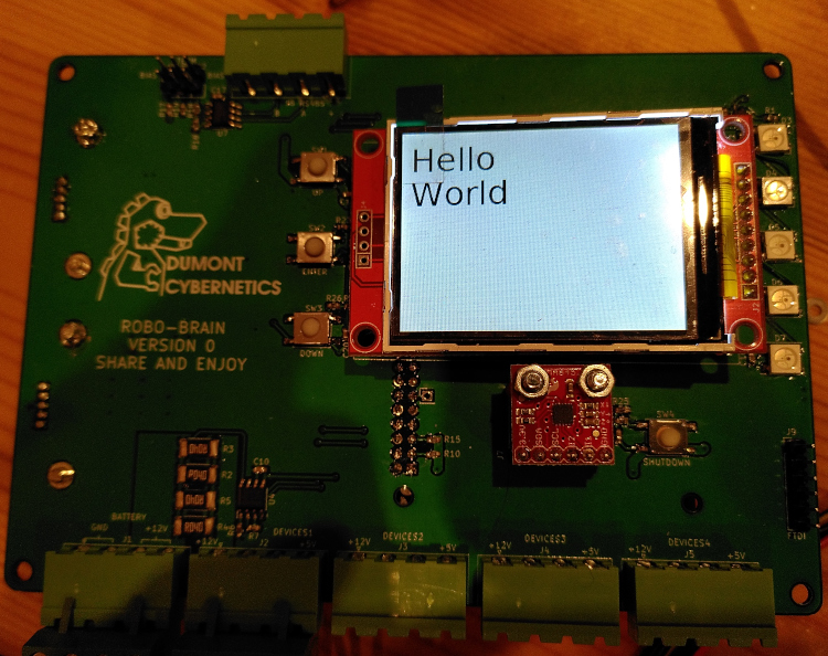
Next I added the example code for multiline text in PIL from https://pillow.readthedocs.io/en/stable/reference/ImageDraw.html#example-draw-multiline-text. To get that working I needed to install PIL and also some TTF fonts for it to work with:
sudo apt install python3-pil fonts-dejavu
Now the LCD demo script looks like this:
import time
import busio
import digitalio
from board import SCK, MOSI, MISO, D8, D22, D25, D27

from adafruit_rgb_display import color565
import adafruit_rgb_display.ili9341 as ili9341


# Configuration for CS and DC pins:
CS_PIN = D8
DC_PIN = D22

backlight = digitalio.DigitalInOut(D25)
backlight.direction = digitalio.Direction.OUTPUT
backlight.value = True

reset_pin = digitalio.DigitalInOut(D27)
reset_pin.direction = digitalio.Direction.OUTPUT
reset_pin.value = True

# Setup SPI bus using hardware SPI:
spi = busio.SPI(clock=SCK, MOSI=MOSI, MISO=MISO)

# Create the ILI9341 display:
display = ili9341.ILI9341(spi, cs=digitalio.DigitalInOut(CS_PIN),
                        dc=digitalio.DigitalInOut(DC_PIN))

from PIL import Image, ImageDraw, ImageFont

# create an image
out = Image.new("RGB", (320, 240), (255, 255, 255))

# get a font
fnt = ImageFont.truetype("/usr/share/fonts/truetype/dejavu/DejaVuSans.ttf", 40)
# get a drawing context
d = ImageDraw.Draw(out)

# draw multiline text
d.multiline_text((10,10), "Hello\nWorld", font=fnt, fill=(0, 0, 0))

display.image(out, 270)
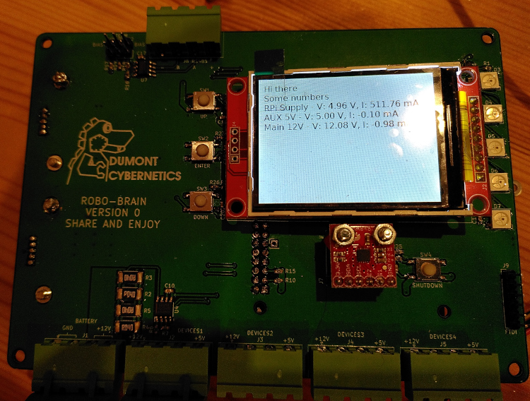
Finally for this part, I installed the pi-ina219 library:
sudo pip3 install pi-ina219
And added some tweaked code to draw the current/voltage from the three power supply monitor chips to the display.
import time
import busio
import digitalio
from board import SCK, MOSI, MISO, D8, D22, D25, D27, I2C

from adafruit_rgb_display import color565
import adafruit_rgb_display.ili9341 as ili9341


# Configuration for CS and DC pins:
CS_PIN = D8
DC_PIN = D22

backlight = digitalio.DigitalInOut(D25)
backlight.direction = digitalio.Direction.OUTPUT
backlight.value = True

reset_pin = digitalio.DigitalInOut(D27)
reset_pin.direction = digitalio.Direction.OUTPUT
reset_pin.value = True

# Setup SPI bus using hardware SPI:
spi = busio.SPI(clock=SCK, MOSI=MOSI, MISO=MISO)

# Create the ILI9341 display:
display = ili9341.ILI9341(spi, cs=digitalio.DigitalInOut(CS_PIN),
                        dc=digitalio.DigitalInOut(DC_PIN))

from PIL import Image, ImageDraw, ImageFont

# create an image
out = Image.new("RGB", (320, 240), (255, 255, 255))

# get a font
fnt = ImageFont.truetype("/usr/share/fonts/truetype/dejavu/DejaVuSans.ttf", 16)
# get a drawing context
d = ImageDraw.Draw(out)

# draw multiline text
d.multiline_text((10,10), "Hello\nWorld", font=fnt, fill=(0, 0, 0))

display.image(out, 270)

from ina219 import INA219

pi_ina = INA219(0.1)
pi_ina.configure()
aux_ina = INA219(0.1, address=0x41)
aux_ina.configure()
main_ina = INA219(0.01, address=0x42)
main_ina.configure()
while True:
    d.rectangle((0, 0, 320, 240), fill=(255,255,255))

    msg = "Hi there\nSome numbers\nRPi Supply - V: {:.2f} V, I: {:.2f} mA\nAUX 5V - V: {:.2f} V, I: {:.2f} mA\nMain 12V - V: {:.2f} V, I: {:.2f} mA".format(pi_ina.voltage(), pi_ina.current(), aux_ina.voltage(), aux_ina.current(), main_ina.voltage(), main_ina.current())

    d.multiline_text((10,10), msg, font=fnt, fill=(0,0,0))
    display.image(out, 270)

    time.sleep(2)
The next step will be to add this as an autostarting script...
Shutdown button
On the PCB is a button labelled "shutdown". Safe shutdown is a critical thing for a Pi, you'll get SD card issues really fast if you don't (depending on brand/size of card how quickly but eventually all will fail). Shutdown without a keyboard or mouse is a common issue for embedded applications though and someone else has done all the hard work. I just copied the instructions from https://www.recantha.co.uk/blog/?p=13999 modifying the pin number in the gpio-halt.service file to 4 which is the GPIO pin I used for shutdown. There's no way to boot it up again after it shuts down because I've not hooked up the wakeup pin (I'm using it for I2C actually) so you've got to kill power by unplugging the battery but that's a good idea anyway in most cases.