With only about 2 weeks to go until the deadline, I started to read the rules in a little more detail to check what we should be submitting. It was at this point I realised we were in breach of the size rules! I'd designed the robot to fill the space allowed but on closer inspection I realised our 4-wheel steering meant that when we steered the back wheels would exceed even the box for "animated attachments". Unless we wanted to beg for lenience or only go in a straight line we needed to fix it, fast.
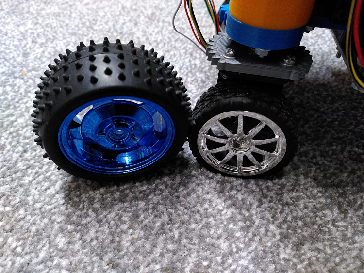
The first, and obvious change was to pick some smaller wheels. Fortunately we found these wheels which would fit our motors nicely which were 20mm smaller in diameter and a little bit thinner too. Changing the wheels wasn't the whole solution though, only 10mm of wiggle room front and back wasn't going to give us much lock, and now the claw dragged on the ground because the robot was 10mm closer to the ground too!
The extra height clearance gave me an idea, we could move the wheels down by 10mm relative to the robot's main platform to maintain our original ground clearance which left room above the wheels for some extra mechanical parts. That meant I could move the pivot-point for the wheels out toward the edge of the robot and place it more over the wheel than over the motor as we had it. This has advantages for clearance, the wheel doesn't get so close to the battery compartment so we can steer more sharply. And it saves us some overall envelope as the steering doesn't make the wheel stick out so far from the side of the robot. Finally it gives the servos a bit of a break, since the wheels aren't moving through such an arc as we steer the force required to turn them is less so the steering servos don't have to work so hard and are more responsive.
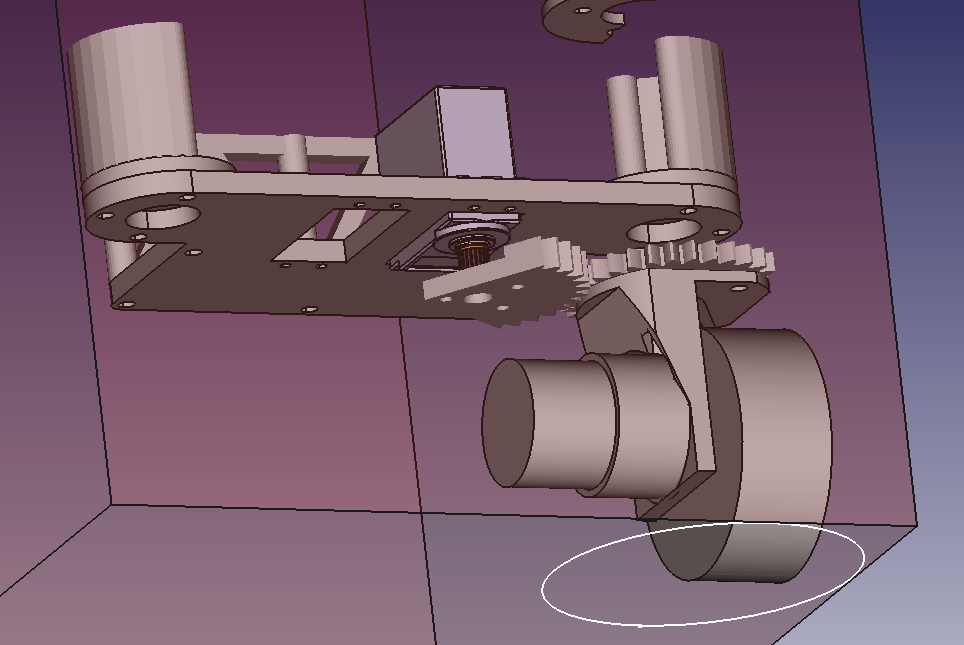
I designed a new motor mount in a "T" shape with the pivot point in the middle. I was sceptical when we started this project about 3D printed mechanical parts but as we've moved on I've realised how strong they are. I printed the whole bracket which of course meant it fit perfectly and I didn't need to do any drilling. I did have to dismantle the whole robot to drill the new mounting holes in the aluminium plate but it went back together quicker than I expected and the improvement in steering handling was brilliant.