
This past year seems to have passed much quicker than the year before. We've not managed to do as much PiWars as I'd hoped, now things are opening up again there have been lots of distractions. As well as all the extra activities I've had a challenging few months after a terrible job move, but things are looking up (and my PiWars 2021 videos formed part of my portfolio for the application!)
We started off with a grand plan to fix all the things that weren't quite right about our 2021 entry. Bigger wheels, better steering, smaller motor driver boards, cleaner attachments. But with any engineering project in the 2020s we hit supply chain and timeline issues. I had learned a lot of FreeCAD last year and the best thing I learned was to start there. The chassis design we entered was basically my first build, there were a couple of tweaks around the suspension but wheel mounts and metal parts are all the first ones I made.
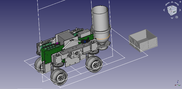
If you'd like to look at the FreeCAD design in more detail, it's on GitHub.
I really wanted to make an off-road capable robot this year. The farming theme and the fact we had access to a real farm for our farmyard tour meant I wanted to do some seriously rough terrain. I had some big wheels left over from last year which we couldn't use because of the size constraints and the amount we extended when steering. Between the end of last year's competition and the start of this I had made a detailed model of the big wheels in FreeCAD ready for modelling a new robot. To get the big wheels into the footprint and still be able to steer all 4 wheels like I wanted I had to switch to worm-drive motor/gearboxes. These had the same torque and speed as the motors we used last year but had output drives at 90 degrees to the body so the motor would stick up in the air, making the whole assembly more compact. What I'd not realised until we were doing obstacles is that the worm drive motors present something of an issue when you stall them. The motor control board we designed last year has current sensing and cuts out if the motor is over current, but when you cut power to a worm-drive motor the wheel locks solid. I was finding it was stalling just one wheel while trying to climb over obstacles or even descending obstacles. It was always the wheel that was under the most strain, so often the one with the best grip but when it stalled it locked the whole robot in place because the other three wheels couldn't drag the locked wheel. I found several times in the obstacle course that I was reversing a little just to take the load of one wheel to free it up again.
Apart from the over-agressive current limiting firmware the system worked really well. I took it for a spin at EMF Camp on the Hacky Racers course and while we placed last I was pleased with how it coped with the terrain. We would probably have achieved much better time if I'd locked the two back wheels and made the front wheel steering less severe. The robot is optimised for the small arena but racing on a larger course I found I was constantly snaking as I over-steered with the very sensitive controls.
I was hoping to make the motor driver boards a little more compact by assembling them slightly differently. They only cost a few pounds each in parts so I was willing to assemble more to get a more compact driver, but they are made of unobtainable STM32 and H-Bridge chips. In the end I had to make do with what we had left over from last year and some DC-DC regulator modules from eBay. I still haven't received the remaining 4 metres of shielded twisted pair RS485 cable I'd ordered to wire the robot up with, fortunately the unshielded twisted pair didn't seem to cause us any issues in the end.
I've still got the long FPC cable I'd bought for the Pi camera to do autonomous, vision based navigation. Maybe another year.