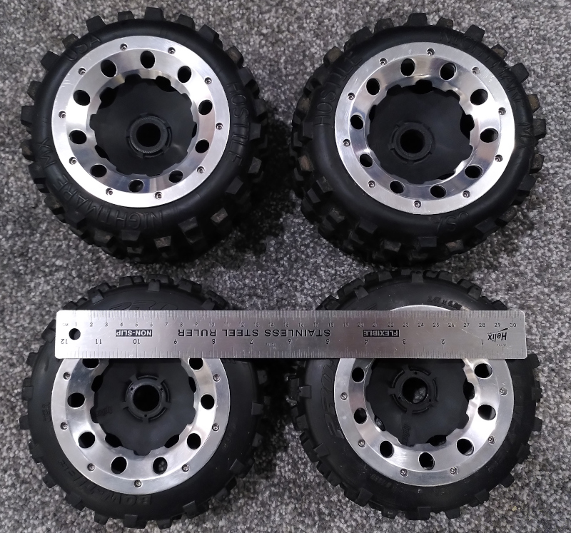
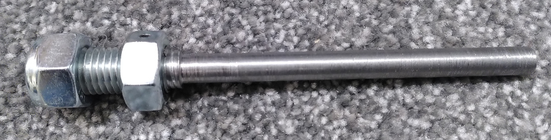
Since the initial trials with a Meccano chassis and some off-the-shelf RC car parts we've been working hard on development of the system. Most of the work over the last couple of months has been in modelling the robot using FreeCAD. Before I could start on modelling we needed to get hold of some wheels (I considered printing some but my printer's not well suited to flexible filament and I wanted grippy tyres). I went back to the local RC shop and got a massive set of 1/5 scale car tyres from the "bargain bin" of second hand parts. These look like a good size fit for the A2 class of Hacky Racer we're aiming for and are well made RC parts. They've got a 24mm hexagon for drive which happens to be exactly the size of an M16 nut, so that's where I started. The axles are designed to be turned from M16 threaded bar and have one M16 nut roll-pinned to them for the drive. A second nyloc nut can then be threaded onto the end of the bar to retain the wheel.
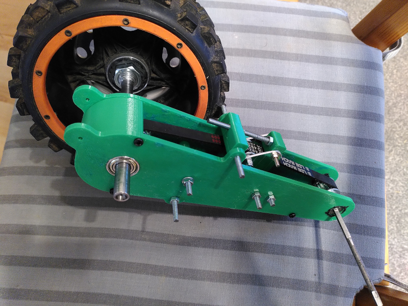
I spent a long time looking at options for power transmission. Most RC cars use a prop-shaft arangement like real cars which drives a front and rear differential in cars that are 4 wheel drive. The trouble with this is that most RC cars are designed to be light and small and tend to use lightweight plastic differential gears which often have proprietary or awkward drive fixings. I don't think Meccano gears would have held up long with my monster wheels and getting hold of steel gears was expensive. Even if we'd bought all the steel gears to build differential gearboxes there was still the problem of building an enclosure for the gears, strong enough to deal with the huge wheels and yet compact and something I could make with my limited tools. 3D printed parts weren't going to cut it here. I explained the problem to John (7) and why we need differential to help us go around corners. He looked at my drawing on the white board for a minute then ran a finger through the back axle and drew a second motor and a laptop and said "we just use two motors and a computer to figure out the speed difference for the two sides". I'd thought of this too and in the end that was the solution we've gone for. We got a second set of motor, speed controller and gearbox and have set the robot up with one motor on each side of the chassis. Now when we want to steer we need a bit of software on a microcontroller to speed up one side and slow down the other, but it means we can "lock the diff" for traction control in software. For power transmission we've gone for 10mm wide 3mm pitch closed loop timing belts. These are like the belts used in 3D printers to move the axes but we're using closed loops that can run around a pair of drive pulleys, one at the top and one on the axle. The belts are much more forgiving than shafts and metal gears and we've added tensioners that mean we can take out a bit of slack so the manufacturing/assembly doesn't have to be perfectly dimensioned to keep the belts tight. This arrangement also gives us full 4-wheel suspension with the chassis connected to each wheel by a lever-arm which keeps the belt tight and a suspension spring which allows the wheel to travel up and down relative to the body.
Steering is another challenge. I went back and forth on the design a bit but in the end we've got a narrower belt enclosure assembly at the front which means the wheel can angle back in toward the body enough to give a good steering lock. I sourced some 10mm diameter universal joints from eBay which will transmit the power through a pair of folded aluminium yokes that hold bearings. Each side has a separate servo since the front axles can move up and down independently and it was much simpler to use two servos than build a big mechanical linkage.
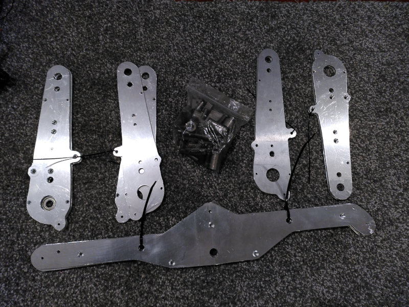
Most of the parts are designed to be cut out of 4mm aluminium sheet. Some of the steering assembly is folded from 2 and 3mm sheet. Finally there are a range of steel spacers which are drilled and tapped that hold the plates together and an array of 3D printed parts for the less structural components. On the top are plates of PLA which bolt to the chassis and have a huge array of sockets for heat-sert thermal inserts which give M3 bolt holes across the surface. It's an idea I took from the Novena open source laptop and is attributed to Nadya Peek.
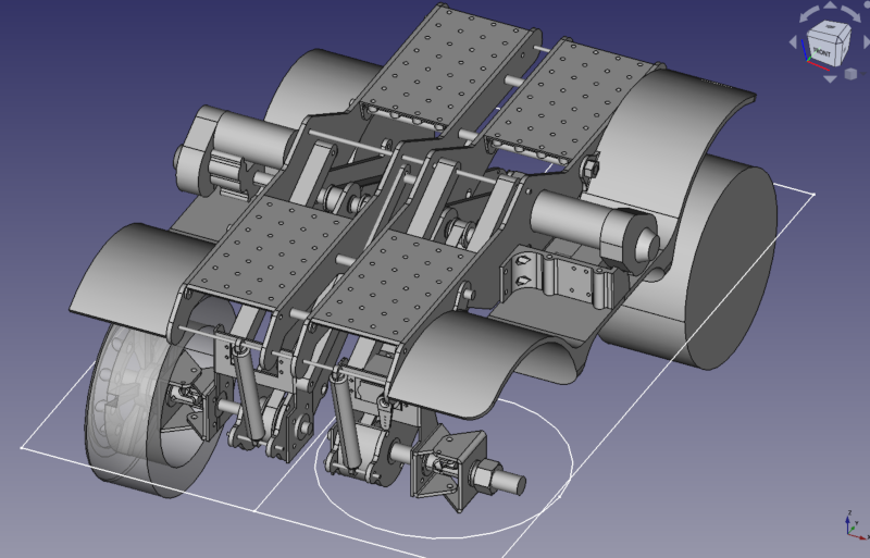
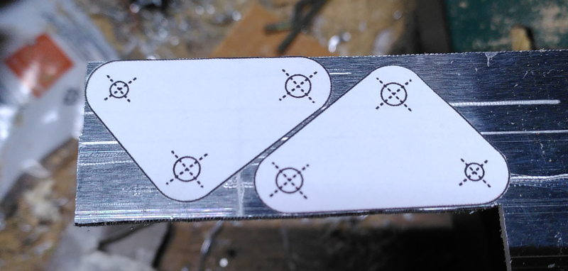
All the design has been done in FreeCAD. I did spend a day or so trying to build the chassis with one of the assembly work benches but the assembly always failed after only a few components. In the end I gave up and just did the assembly myself by enclosing all the bodys inside parts and using the link parts feature that's appeared in the latest release. I used the transform tool to make the suspension arm assemblies and the steered wheels pivot on their axes. That meant I could easily rotate the whole wheel sub-assembly around the axis of the steering pin and found several clearance issues. Similarly I rotated the belt arms around their pivot to simulate the suspension springs compressing and found more clearance issues. This is definitely the most complex design I've created in FreeCAD (although I've imported some bigger ones for work projects) but on the whole I've found it pretty reliable and easy to use. FreeCAD has made huge progress over the last decade. One workbench I found really helpful was the sheet metal workbench. I've used that for the folded aluminium parts around the steering. I'd designed the parts using the normal Part Design workbench pad and pocket tools, but I've done enough metalwork to know I needed to allow for bends and clearances at corners etc. What I couldn't do with my designs was "unfold" them though, using the sheet metal workbench that becomes easy, then I can use my tried-and-tested print out the drawing 1:1 on sticky label and drill/saw/file the parts in the shed.
For the larger parts I've outsourced the manufacture to my dad. Partly because he has a better equipped workshop and partly because with work and family I just don't have time to spend in the shed filing down bits of metal. I produced detailed drawings from the FreeCAD design and sent them over to him and he's cut out the parts and then used his milling machine with Digital Read Out (DRO) to precisely drill the holes as I'd designed. The precision is pretty important on this design because the tensioning of the belts is tricky. I went through three prototype fittings before I settled on one that tensioned the belt the way I wanted and it was just 0.5mm longer than the original design. Because the length of the belt arm takes out twice as much slack in the belt (there and back again) you can change the belt tension quite dramatically by adjusting it just a little. I had it nearly right initially but when I made my first trial I mis-drilled the hole by nearly 1mm so the belt was far too slack. The tensioner can take out about 3-4mm of slack but mostly that's there so that the assembly isn't too hard, I had over 6mm slack on that first design. I lengthened the belt assembly by 2mm and this time I 3D printed the side plates. That means I've got good dimensional accuracy but the parts won't be strong enough for use. This time the belt was way too tight, I could barely get the assembly together. I spent several days scraching my head at this point before finally going back and measuring the slack one and discovering it was drilled short. After that I tried another design very quickly and roughly cut from some pieces of MDF I had in the shed which again was too tight to assemble before finally settling on a design just 0.5mm longer than my initial design, this time I made all the parts on the 3D printer and did a test assembly before sending drawings off to dad for manufacture in aluminium. This highlights how easy the tools are to use and how far ahead of the typical home workshop the tolerances are! (Although if I'd been in less of a rush making the first one I probably could have made it a lot more accurate. I'd tried to go straight from center-punch to a 10mm drill but I should have used a smaller drill to follow the center punch and open it out for the bigger drill bit.)
Now I've got a big pile of aluminium parts, some wheels lots of bolts and suspension parts, bags of bearings and some motors. I'm still lacking a number of large 3D printed parts, mostly mud-guards to keep the dirt out of the moving parts, but the 3D printer is in need of some work. (It's out of filament and still has a 2.85mm hot end, which seriously limits the places and range of filament available). Once I've got the new hot-end and extruder working I can return to robot assembly. Then there's just the electronics, power management and software to do!