
The latest challenge was to get the screen working. This section had a pretty big number of parts to add to the board, including the HDMI/DVI transmitter which needed soldering down to a large thermal pad under the chip. I did the pad using some low-temperature solder paste and the miniature hot plate. That part seemed to go okay then the pins round the transmitter chip I soldered down one by one with a soldering iron. I filled in all the passives, the ESD protection chip and the HDMI connector. There's also a power-only USB A connector next to the HDMI. I fitted that, it's designed to power the HDMI to LVDS conversion module that comes with the LCD I have (from Pimoroni).
The screen output on my board is probably the most complicated section of the board. I've got a full HDMI connector and I'm planning to drive the 10" 1024x768 LCD. The STM32 has a peripheral called the "LCD TFT Display Controller" (LTDC). This peripheral will generate up to 24bit parallel RGB output along with standard pixel clock, Display Enable (DE) and horizontal and vertical sync signals. This kind of signal can be piped straight into some sorts of displays, the Hyperpixel display range from Pimoroni uses this interface for example. I wanted to drive a bigger screen and have some flexibility to use other screens though. I found the TFP410PAP DVI transmitter chip from Texas Instruments which can take parallel RGB data and generate the differential signals needed to drive a DVI display. HDMI uses the same signalling as DVI but with added audio, if you don't need audio then you can just wire the DVI transmitter to the HDMI connector.
Getting the transmitter to work
The TFP410 can be used in a couple of different ways:
- As a simple device with all options hard coded with strapping pins pulled high/low
- As a programmable device with an I²C interface
I'd laid the board out with the second option in mind but looking around it seems most of the other open-source projects using this chip had gone for 1 (see DVI PMOD). I found I had two things to do before I could generate a signal with the chip:
- You have to send it a reset pulse after start up. This was easy to do, I had a GPIO attached to the reset line of the driver chip.
- You need to write the control register to enable TMDS interface (HDMI/DVI transmitter, see TMDS - Wikipedia) by setting bit 6 low and enable the chip by setting bit high.
Once I'd figured out that it was pretty easy to use the standard HAL routines to write the register and read back some diagnostics from the chip's registers.
Driving a full colour display
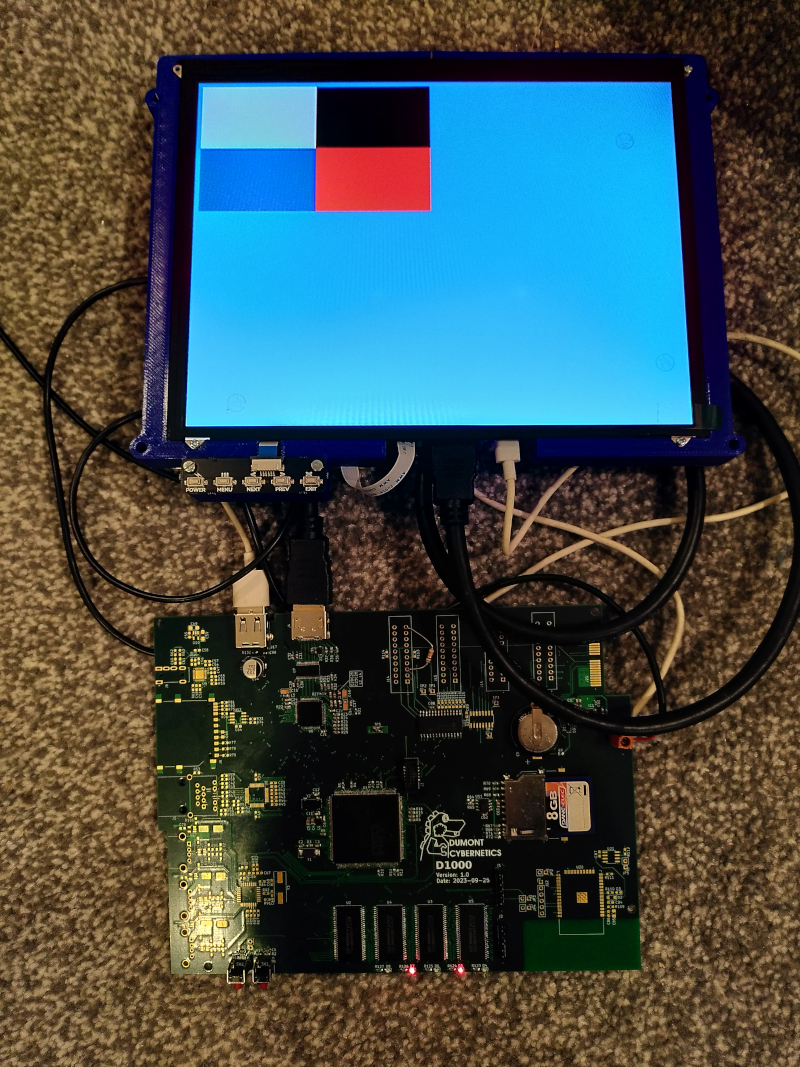
Next I focused on getting the display to show something. I used CubeMX and played around with the settings a bit to learn how the LTDC peripheral works. I found this LTDC Application Note which goes into detail on the way the peripheral works and some of the limitations. Table 12 in that document gives some details about the maximum pixel clock and the possible bit depths. I've got 32bit SDRAM which is good, it means maximum memory bandwidth is available. I found a VESA specification and on page 33 found the timings for 1024x768 at 60Hz. I needed a pixel clock of 65MHz. Setting that and the vertical and horizontal sync and porch timings I was able to get something to display. I set up a small window in one corner of the display and a background colour using one of the programmable layers. According to the applicaiton note I didn't have the bandwidth to do two layers at 32bit colour depth. I spent a little while trying to figure out the format for the frame buffer. It turns out it's just 4 bytes (alpha, red, green and blue) for each pixel, the stride registers which for some reason add 7 to the number of bytes don't actually apply to the row stride. I wrote a simple test pattern to write four colours to the four quarters of the window. I could see the window and the background colour but the window was not showing what I expected. After a bit of testing out what was actually in memory I decided it was all right, but the bandwidth wasn't enough. I fiddled with the settings a bit and found that I'd set up the SDRAM with a CAS latency of 3, but I could turn that down to 2 with the 100MHz clock I'd used. Once I'd done that the display suddenly solidified into a clean test pattern.
How about text
The full colour display was working but it was using the vast majority of the memory bandwidth even if there is plenty of memory spare. There's also not much point in using the windowing features of the layer unless you want to do something like letterboxing to save memory. I wanted a full screen frame buffer but with much lower memory requirements. Reviewing the app note again I found the 8 bit colour look up table mode (CLUT). In this mode each pixel is represented by only 1 byte in memory (reducing the memory bandwidth requirements by 75% vs a full 32bit per pixel display). This byte is read from memory and then converted to a full RGB colour by looking up the byte value in a 256 entry look up table. The look up table can be in faster memory on-chip since it's only a few hundred bytes. I did a couple of tests just filling the screen with colours from this look up table and it looked very nostalgic, similar to the output of BBC basic programs I'd written on an A3020 many years ago.
What I really wanted to be able to display was text. A serial console on the display is where I'm heading for now. I broke out my trusty fontedit tool for making bitmapped fonts and started on an IBM BIOS inspired 8x16 font. The tool I wrote can spit out C code which represents the font as an array of strings of 16 bytes, each 16 byte string represents one character and each byte represents one row of the character. A 1 bit indicates foreground colour a 0 represents background. With the font in my code I wrote a really simple for loop to convert the 0 bits to 0x00 (mapped to RGB black by the CLUT) and the 1 bits to 0xff (mapped to RGB white) in the new framebuffer where each byte was a pixel.
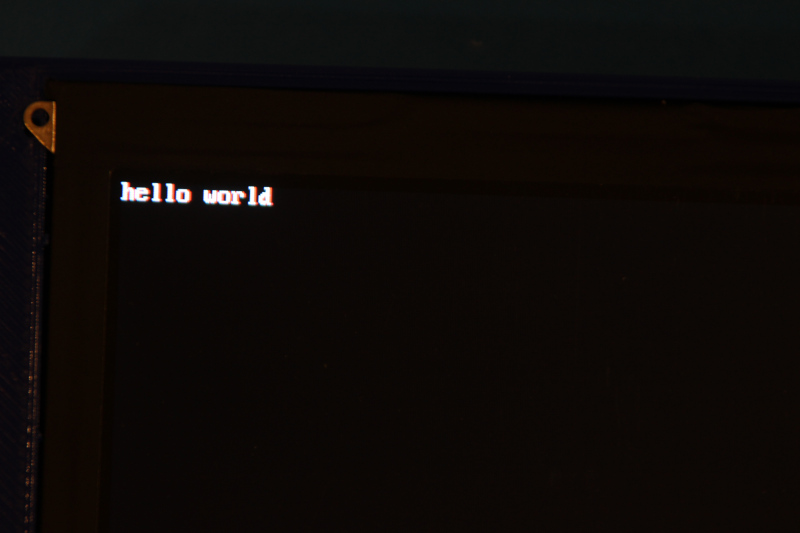
With this font in place the screen is ready to do something useful. I've still got some work to do on the extended characters that were a thing in the BIOS font, characters for drawing boxes and frames that were used in CLI interfaces, but the core ASCII values are in.
Structure of the code
I've implemented all of this in the Cortex-M4 core. I added a UART interface (UART6 on the "AUX" header) which is managed by the Cortex-M4 and set up as stdio. That means if I call printf() on the M4 it comes out on the AUX header but I can use it to debug values. I also added a hardware semaphore which I gave when the M7 had finished performing the memory check so that the screen filling routines didn't run until after the memory test (which would overwrite the screen buffer) was finished.
My plan is to use the Cortex-M4 as a GPU offering basic text rendering for now but maybe some more advanced graphical operations or even a basic 3D renderer. I think I need to provide two interfaces through shared memory to the M7;
- A bidirectional interface like a socket which I can use for sending commands (display on or off or set display mode for example) or read information (see what monitor is attached).
- A unidirectional high-bandwidth interface to shove data into the GPU.
I could use something like OpenAMP for this but maybe all I need is to read a little more on the hardware semaphores.
Next challenge
I'm going to tackle the USB host next. That's only a 2 pin interface on the STM32 but there's a 3 port USB hub on the board to give 3 Full Speed (12Mbps) USB host ports. I want to be able to plug a USB keyboard in to complete the local console functionality.
You can see the latest code at this commit on GitHub