
Now that I have the PCBs and all of the parts its time to start bringing up the board. The good thing about using a microcontroller over a less integrated microprocessor is that I can bring it up on its own to start with. All I need is power supply and a few passive components like the pull-up on the reset pin.
Power supply
The power supply design is really simple, there are only 3 voltage rails in the whole board 1 (compared with 8 on the RPi 5!). There's 5V which I've just assumed is provided from an external supply and is fed directly to 5V subsystems like the USB ports and the HDMI connector. There's a tiny 2.5V linear regulator which is just used by the audio codec. And there's 3.3V for everything else. I've used the new TI Simple Switcher LMR51430 switch mode regulator for my 3.3V rail. I've used Simple Switcher series of regulators for decades but this latest generation is astonishing, the SOT23-6 chip can supply up to 3A with a tiny inductor and only passive external parts.
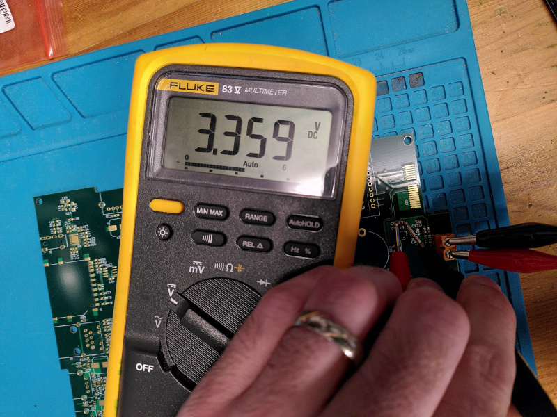
I built up this main power supply and added the external screw terminal connector to start with and then checked the voltage across the output capacitor to make sure I'd assembled it right and that the output setting resistors were right.
MCU
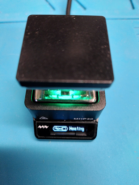
The microcontroller I've chosen is the STM32H745BIT6. It's a dual core beast with a Cortex-M7 running at 480MHz and an M4 at 240MHz in one chip. It has its own switch mode power supply to deal with the amount of power needed on the lower voltage internal rails which just needs an inductor as well as the usual array of decoupling caps for an STM32. It's a 208 pin LQFP so there are a lot of pins to solder. I did the decoupling capacitors first, appart from the ones directly related to the internal PSU these are on the back of the board. I used my mini hot-plate at 250°C to warm the board up so that soldering these caps between power planes wasn't too hard.
With the caps on the back on I started soldering the MCU pins. There are a lot. I tried using the hot plate to warm the board up a bit but I couldn't put it directly under the MCU because of the decoupling caps on the back of the board. The first two sides went farily badly, I tried drag soldering but I don't think my iron was really hot enough and I ended up with lots of blobs of solder which needed wicking off and then ended up bending some pins doing that. For inspection of my dodgy soldering I used the Engineer SL-71 PCB Inspection Loupe which works well for inspection but only when it's sat on the board. The second two sides went better, probably I got more used to using the soldering iron at home again. I put a generous helping of flux on the pins then carefully soldered each one separately with the 0.4mm tip on the iron. To help while soldering I used my trusty helping hand with magnifier. Eventually all 208 pins looked good under optical inspection, hopefully they'll all be okay electrically!
With the MCU on and the decoupling and 3.3V regulator I just had to add a few passives to get it going. I fitted the SWD header, the reset switch and associated resistors and capacitor, the crystals and their caps and the inductor and capacitors for the internal PSU. Finally I added the supercap, diodes and resistor for the RTC and the resistors on the PDR_ON and BOOT0 pins.
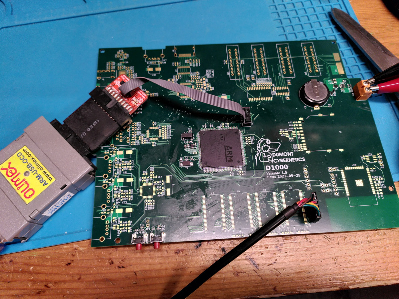
I attached my trusty old Olimex ARM-USB-OCD with the SWD adapter and a 20-pin to 10-pin adapter to the SWD header and a 3.3V FTDI USB to TTL level UART cable to the Console header. I hadn't soldered the console header yet, I'm just relying on the tention of the cable to keep the pins in contact for now. I think it will be in the way when I start trying to solder the SDRAM.
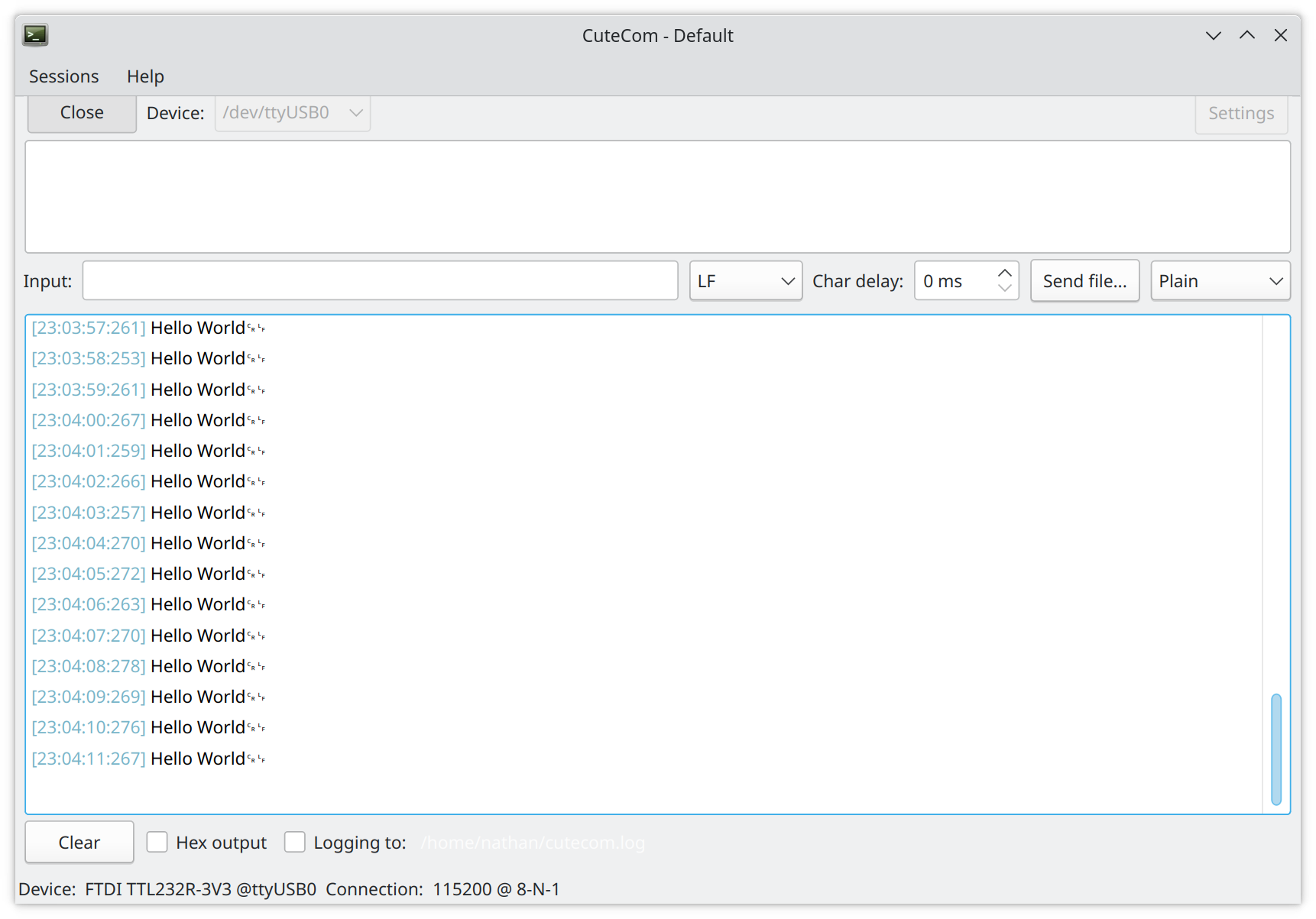
I'd prepared an STM Cube project which set up just UART3 which is connected to the Console header and sits in a loop printing "Hello World" once every second. You can take a look at the code I wrote in this commit on GitHub. Most of the code here is auto-generated by Cube MX. I set up FreeRTOS (not sure I'll stick with Cube's version of this but it'll do for now), debug interface, UART and system clocks in CubeMX then generated the code. I'm not using the provided Makefile, I prefer CMake so I've written my own CMake top-level file which builds two images from the source tree, one for the CM4 and one for the CM7. That makes two *.hex files in the build folder. I then wrote a really simple bash script which uses OpenOCD to flash the two Hex files one after another. The STM32H745 has two flash banks and by default points one core at each to run code. There's a sort of two-way hand shake generated in the CubeMX code which starts both cores then makes the CM4 sleep until the CM7 wakes it so that the CM7 can configure any shared resources. I've not modified any of this support code, just using it as it comes from ST at the moment, but that means I do have to make sure that both cores get their code flashed.
I plugged in the power and watched the current, in reset it only draws about 10mA, as I was expecting. Once I'd flashed the new code in the power consumption jumped up to 90mA! It's a lot for an MCU but actually that's normal for this chip, I've got it set to maximum power consumption, top speed and both cores running in this test although they're mostly spinning in loops waiting.
Plugging in the UART header rewarded me with a friendly message, so phase one is complete.
Now I've got the MCU working I need to do a little work on my console code to make it possible to run some commands. I can then start to make some basic system test commands to check out the RTC which is wired up and then move into fitting and testing out the SDRAM.
-
Actually there are more than 3 because some of the chips create multiple rails for their own use but there are only 3 that I've designed at board level. ↩