
We've been rushing to get some hardware working in time for the deadline and neglecting the blog in the process. Due to one thing and another we've had less time to work on the robot than we'd hoped. Now with the delay of the official competition date we've got room to breathe!
Servo driver tests
The motor driver board is now running servo control, the first version of code did a test pattern scanning the servo back and forth in a for-loop. We're using one of the built-in hardware timers so you just have to set the duty register to update the angle. One of the first things we did once that was working was a quick torque test to see if the servos we'd chosen were strong enough. This didn't go well. The servo was plenty strong enough but, despite buying "all metal gears" parts from a UK seller on eBay the servo started making funny noises like it was missing teeth. Upon closer inspection it was of course all plastic gears apart from the last one which had chewed the teeth of the last one before it.
With the competition looming (or so we thought) we just ordered a new set from ThePiHut who delivered extremely promptly with genuine parts.
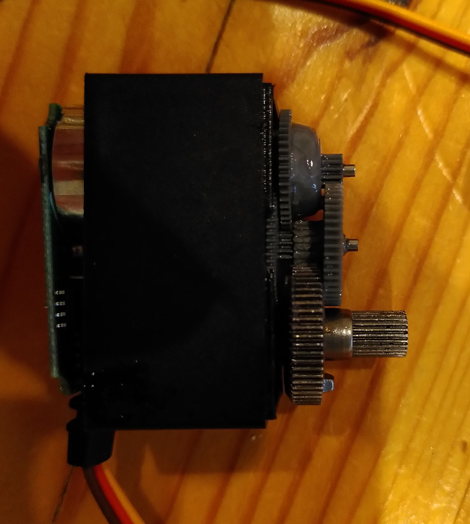
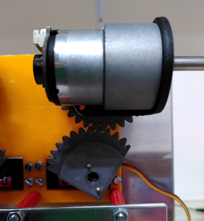
Next we experimented with various linkages and servo horns to connect up the steering servo to the motor/wheel assembly. Mostly we had slop issues but there were also geometry issues. We initially had the servos mounted with the horns above the lower plane of the chassis with the linkages between the two plates we built our chassis out of. This was a real pain for disassembling the wheel/motor assemblies. After some head scratching I realised we had a 3D printer and could make gears. We used an OpenSCAD library for creating gears and put mounting holes for the motor plate and sliced one so it was only a ~100°ree; arc with mounting for the servo horn. Now the servo had direct 1:1 control over the wheel angle with minimal slop and the gears fitted under the bottom chassis with the servo upside down making removing wheels trivial.
H-Bridge tests
Next was testing the main motor driver boards. We designed around an eval-board for the ST VNH7070AS, an automotive-qualified 4A full H-bridge. This just needed some headers soldering in and then plug it in the back of the control board. This was a breeze to get going. It has a dedicated PWM input as well as the two control inputs for direction/braking/freewheel and the inputs are all 3.3V logic compatible. Lifting the PWM code from the servo driver I tweaked it to run at 10kHz, the H-bridge says PWM up to 20kHz is fine but I don't want to get too close to the limits, 10k is fine. I set the duty up to give us 400 steps between stopped and full speed and wrote a demo loop that runs it up from 0 to full speed, down again then reverses the direction and repeats. It all worked cleanly and nothing blew up!
If you stall DC motors they're basically just a wire across the supply and tend to get hot pretty quick which can damage the windings. The H-bridge chip has a current mirror which outputs a current approximately 1500 times smaller than the motor current. This is fed into a resistor to create a variable voltage which is read by an ADC on the motor controller so we can keep track of per-motor current consumption. With the help of the INA219 current sensor attached to the Pi and the script we wrote I got the ADC reading calibrated so now we know when the motor is over-current and can shut down the PWM output to reduce the current until the stall is over. This is done in principal but still needs testing (so it's not done).
Chassis creation
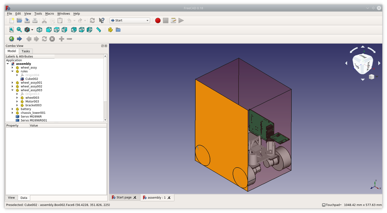
I've been fiddling with the chassis design in various tools since we started. First off was a very rough sketch in Inkscape which gave us an idea of whether the motors would fit in the outline defined in the rules. From there I moved into FreeCAD to start a 3D model and added the motors, battery and servos.
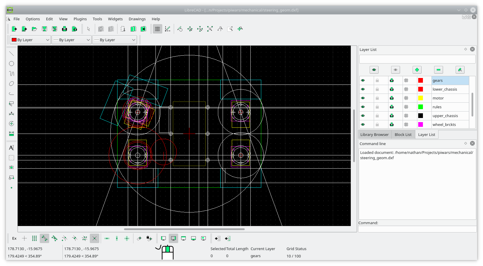
I also did a top-down drawing in LibreCAD to help me get my head around the steering geometry. This was important in helping me figure out how far around the wheels had to turn to get it turn on the spot with no sideways force on the wheels. It also helped figure out the shape and space I had when the wheels were in each lock position.
My favourite tool for 3D printing design is OpenSCAD so I started designing a chassis end design in this. My idea was to split the robot around the battery. A flat sheet of aluminium would make the top layer of the motive platform, the battery, motors and steering servos would all live below this. The design is symmetrical as well. I designed a flat block with cutouts for the two steering servos and press fit rebates for the 6mm bearings which will carry the wheel assembly pivot points. I made more press fit bearing holders to sit on top of the aluminium sheet as I didn't want to have that thick enough to embed the bearing nor did I want the expense of flanged bearings. There are then some frameworks to hold this plastic sub-assembly below the aluminium plate. They're only strong in compression but they have 3 M4 threaded rods running through each of them. Finally there's an aluminium floor for the battery to sit on with a thin printed guard to keep the battery in and some more printed pillars to space it out to the right height. Again there are threaded M4 rods all the way through from the top plate to the bottom.
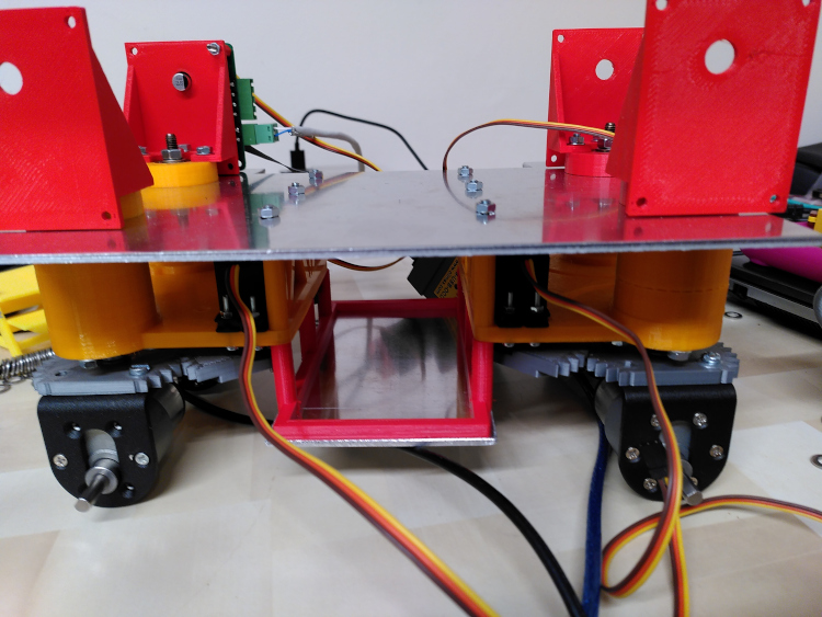
With a mix of orange and red fillament it's a bit of a mish-mash but it all holds together. I experimented briefly with storing the motor drivers in the gap between layers but there just wasn't room with the layers of PCBs and the biggish decoupling caps on the motor board. In the end I printed a sort of sideways shelf that sits on top of each bearing mount to hold the motor driver. This keeps them out of the central area where we still hope to have a telescopic arm. With the printed steering gear and sufficient input from the pillar drill the assembly all came together. I also discovered you could dis-assemble the motor from the gearbox and flip it 180 degrees (the output shaft is off-center so if I just mounted it the other way up the wheels would be at different heights). Flipping two of the motors makes the wiring harness from the motor reach the controller cleanly without catching in the steering gears.