We've already discussed what motors we're using. These motors need some fairly hefty speed control, they have a stall current of 3.4A. They've also got magnetic encoders which means we need real-time encoder monitoring ability. Real-time stuff on the Pi is challenging, and monitoring 4 quadrature encoders with one Pi will be a very tricky job. For the four wheel steering design we have in mind we also need a servo for each wheel. Our plan is to delegate each wheel; encoder, motor, and steering servo, to a separate microcontroller. These microcontrollers will then accept commands from the Pi, something like "go forward 1 metre at half a metre per second bearing 20 degrees". The Pi will then be responsible for calculating all these headings, speeds and distances to keep the platform moving smoothly but won't have to worry about the details of keeping up the servo control pulses or counting the encoder pulses. This is a bit like how a 3D printer delegates the nitty-gritty detail to the microcontroller on the electronics board which understands instructions (often in a language called G-Code) that are like the example above "go here at this speed".
To drive the motors forward and backward we need an H-Bridge, I wrote a tutorial about them a few years back, but we need to handle more power than the L298 and L293 I discussed in that article. I've found a decent H-Bridge motor driver chip from ST which is suitable for the current we're going to need. It appears to have been made for motorised adjustable car seats. Fortunately it's available as an eval board with 0.1" pitch headers because these SMD power control chips all need a thermal slug soldering to the PCB which is really hard to do reliably without a decent reflow setup. We're going to use RS485 to connect up the different motor drivers to the Raspberry Pi. RS485 is easily available and uses a standard UART on the Pi and microcontroller. It is also designed for a multi-drop bus, so we can connect all the motor drivers to the same UART on the Pi. Most importantly, unlike I2C which is similarly suitable for multi-drop comms, RS485 is a robust, balanced signalling standard. 0V levels and comms lines can be pretty noisy in a small robot where the relatively thin wires are connecting up different bits of circuitry spread out with big currents rushing around. RS485 was designed for use in industrial situations and is resistant to this kind of interference.
To monitor the motor and control the H-Bridge and servo I want a microcontroller which has:
- At least one UART for the RS485 comms, preferably 2 because having a debug UART is always handy
- A quadrature encoder capable timer/counter peripheral, this takes the pain out of counting pulses
- Another timer/counter for PWM to drive the H-Bridge PWM input which allows variable speed control instead of just backward-off-forward
- Yet another timer/counter for PWM to drive the servo signals
- An ADC peripheral to monitor current from the H-Bridge current sense output would be handy
- A few extra GPIO for debug LEDs, direction control pins on the H-Bridge, 485 drive enable etc.
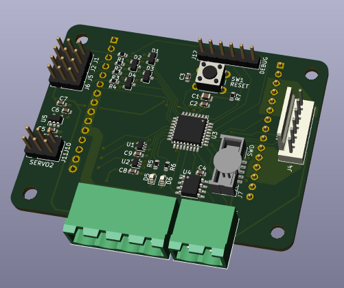
I found the STM32G071KBT6 has all these peripherals and is a neat little 32-pin package. I verified the peripheral assignment in the STM32CubeMX design tool. I've designed a small PCB with the microcontroller, the connectors for RS485 comms, power, motor and the H-Bridge eval board and a few extra buffers, protection components and a 3.3V regulator so that we only need to distribute 5V and 12V around the robot.
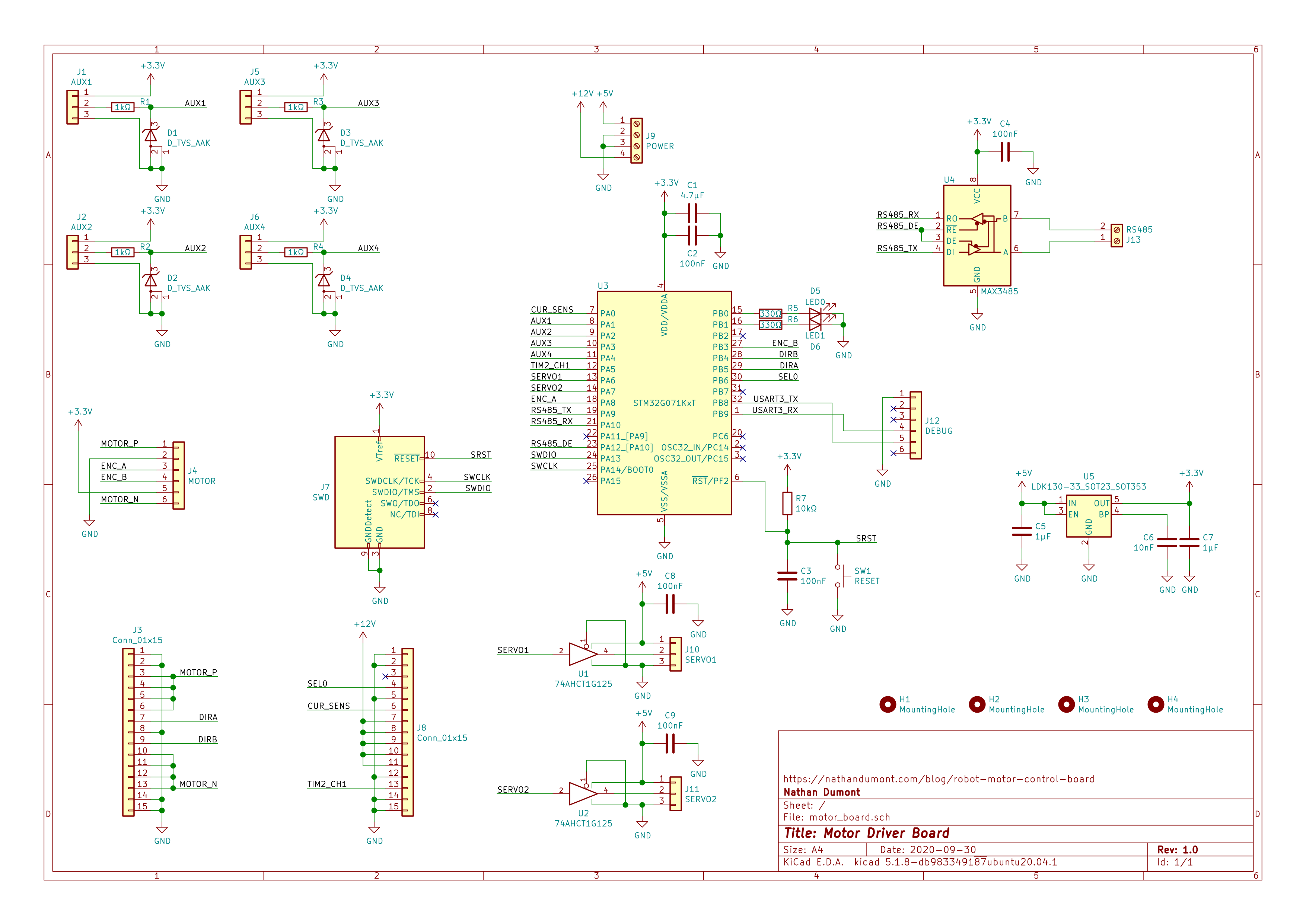
I've ordered the boards as bare PCBs from itead and will populate them myself.