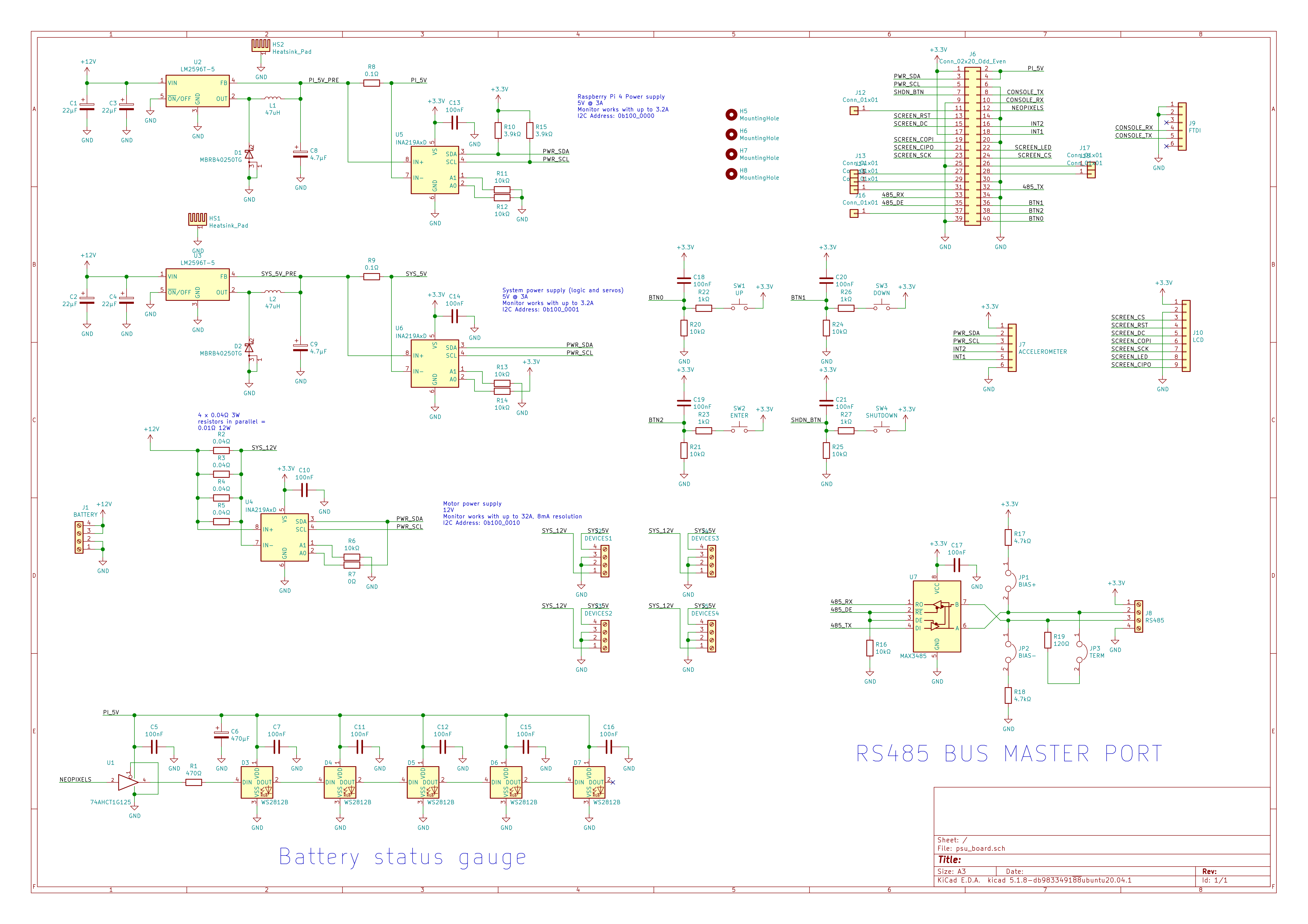
Having designed the motor controllers the last main chunk of electronics needed is the stuff that wraps around the RaspberryPi. We're planning on using a Pi4 for two reasons. One is that we hope to exploit its processing power with a camera to do some tasks autonomously (time will tell if we get that far!) and also the Pi4 has a number of additional peripherals on the GPIO header, particularly we want a second UART. I'd like to run the Pi off the same 12V battery as the motors to keep the weight down, but that means we need a chunky 5V regulator. We're also running a bunch of servos and the motor driver boards derive their 3.3V logic power from a 5V input so we need some extra 5V capacity for those things. So on the controller board we want:
- A Pi GPIO connector to fan-out the contacts we need and to power the Pi4 without needing a USB-C connector
- A 5V 3A supply from the 12V lead-acid to power the Pi
- A 5V supply for servos and control electronics
- Some power distribution for the 12V straight from the battery
- Battery level gauge, a set of LEDs that light up depending on how much battery is left
- An RS485 driver hooked up to UART5 on the Pi4 to talk to the motor controllers
- Current monitoring (INA219) on the two 5V supplies and the 12V rail
- Some buttons to interact directly with the Pi without having to SSH or get a screen/keyboard
- A small screen to display status info, I've got a couple of these lying around
- A debug UART on the standard UART pins, if we enable serial login on the Pi and put an FTDI compatible header we can plug in a cable (I already have) for serial console at very little cost.
- An accelerometer would be good to help with steering, most (if not all) the MEMS accelerometers on the market are tiny leadless packages which are really hard to solder by hand. A breakout like the SEN-12756 board from Sparkfun is easy to solder and cheap enough.
I want to be able to build up just one of these boards at home without a reflow-oven so I want a 5V power supply that doesn't need a thermal slug soldering. At 3A minimum we have to look at a switch mode power supply, from 12V to 5V at 3A would be 21W of heat, more wasted in heat than used by the Pi! The best solution I found is the venerable LM2596. These are still available in TO220 through-hole packages and can do 3A at 5V. The switching frequency is lower than more modern parts which means the inductors are physically bigger. There's not a bigger current option either, so we need to use 2 of them to make power for the RPi and servos separately, although that's not necessarily a bad thing.
To keep track of the battery level I've added 5 LEDs. I wanted to have red/green to change the colour to red as the battery level drops. In the end the easiest solution (and cheapest) I could find was to put 5 WS2812B "Neopixels" on the side of the board. These hook up to just a single pin on the Pi and can be controlled brightness and full RGB colour.
I've added a bunch of terminal blocks for hooking up the motor boards. They don't have to be one to one, these connectors are rated for up to 3 motor boards each but more connectors makes for less spaghetti wiring.
We've got the small SPI LCD as output and 3 buttons next to it that could be used to run a simple menu to control the Pi directly. There's also another separate button labelled "Shutdown" which will be hooked up to a script that does a safe shutdown when pressed to save the SD card. Once the Pi is shutdown it needs to be powered off (by unplugging the battery) before it will boot again. We can't use the wakeup button easily as it conflicts with the I2C bus.
On the I2C bus we've got 3 INA219 power monitor ICs. These measure high-side voltage and current via a low value current sense resistor. There's one each on the two 5V regulators which can measure up to 3.2A current draw. The third one is on the 12V supply to the motor power connectors. The high side voltage will also give us the battery voltage for battery level sensing. The 12V monitor can measure up to 32A. 32A is a big current, we shouldn't hit this, but to be safe the sense resistor is rated for the full 32A.
P = I² R = 32A² × 0.01Ω = 10.24W
To keep the sense resistor cheap I've placed 4 0.04Ω resistors in parallel, they're each rated at 3W so the total rating should be 12W and the resistance is 0.01Ω as intended. In practice the most we expect to measure is around 12A if all 4 motors stall simultaneously.
Headers for the debug UART and the accelerometer are included. As well as a standard MAX3485 compatible footprint for the RS485 driver chip. There are jumpers to enable various termination resistors for the RS485 bus. RS485 busses are designed to be daisy-chained from device to device in a screened cable, but to stop the screen creating a ground loop it should only be grounded at one end and to stop echos bouncing off the ends of the line each end should have a 120Ω resistor across the two conductors. There are also pull up and down resistors included to pull the lines to an idle state if there are no talkers enabled.
Finally the Pi will mount to the PCB via its 4 mounting holes for reliability whilst the robot drives around and I've used a tall 40 way pin header to offset the Pi so it can fit, ports and all, below the controller board. These tall headers are left-over from the PC104 era but work well for the Pi. The heatsinks for the 5V regulators are also slung under the board so we'll have a fairly clear top surface for the screen and buttons. I've added an illustration of a robot dragon in the silkscreen which John is particularly excited about.
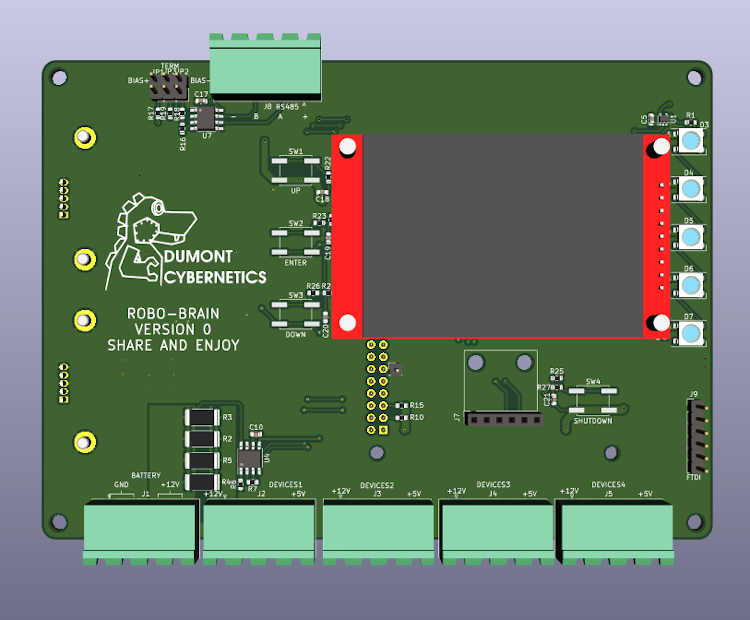
Boards are coming from JLC PCB this time, they're big-ish at 100 x 140mm but only 2 sided and not very tightly packed because of the bulky components.